OBD GENERATION 1
In order to have greater control
of fueling to achieve emission standards .
microprocessor control systems
were developed by :-
bosch
ac-delco
ford -
To name but a few, these systems all differed in one way or other but they all controlled the fueling by acting on information supplied by various sensors.
input signals involved
engine speed + crank angle
engine load
water temperature
air temperature
air mass or quantity
Camshaft sensor (only used for
sequential injection on multivalve engines)
in some cases vehicle speed.
The control unit takes all these input signals and calculates the following :-
Ignition output and advance to drive
the coil into collapse condition to create a spark at the correct time
injection pulse to drive the injector/s
open for the correct length of time (pulse width or dwell)
At the same time the ECU is looking at a mapped reference if at any time it see,s anything that it objects to, the management warning light will be illuminated to warn the driver at which point the engine may go into limp home mode and start running roughly this would depend on the particular fault that had occurred.
If after the engine cools
down and the ECU still see,s a fault the engine may not start at all (fault
dependant)
with onward development of engine control systems (closed loop operation) was introduced to bring even greater control to fueling requirements , engines running correctly will conform to something called stoichiometry which is an air/fuel ratio of 14.7:1 to achieve this an oxygen sensor is placed in the exhaust system in front of an item called a catalyictic convertor for more information on CATS refer to Bath university.
and also see Eurocats
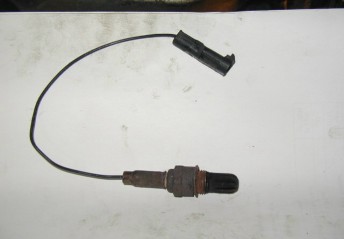
below you will see an oxygen(o2
sensor) this is yet an other input signal
This o2 sensor is at the heart of the closed loop operation, it looks at exhaust gas passing over it when it see,s o2 it generates a small ac voltage which the ecu uses to modify injection pulse width to conform to stoichiometry see below the curve of stoichiometry with kind permission of the spx corp. (bear diagnostics)
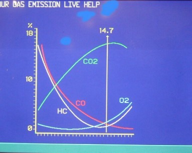
O2 = OXYGEN
CO2
CO = CARBON MONOXIDE
HYDRO CARBONS
HC IS ALSO KNOWN AS UNBURNT FUEL
An other name for stoichiometry
is lambda 1
And thus the O2 sensor often gets
called the lambda sensor.
The air
we breath consists of 20% O2 therefore on a four cylinder engine each cylinder
will receive 5% thats the theory .
however
in reality even an engine that is brand spanking new will never ever
have complete burn properties and as a result you can expect to see up
to 2% O2 residue in exhaust gas analysis
back
home